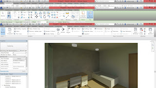
Project 01: Case Study: Basic building design strategies 


Objectives   
The objectives of this project are: 
• To identify and define the principles of heat transfer in relation to building and people 
• To understand what is thermal comfort and discuss factors relating to thermal comfort 
• To analyze the effect of thermal comfort factors in a person and in a space 
• To be able to criticize design of the space in terms of thermal comfort by referring to MS1525 , UBBL, GBI and Green Mark standards.  

Learning Outcomes  
Upon successful completion of the module, students will be able to: 
1. Identify environmental conditions related to site conditions, climate, etc. 
2. Explain the effects of the sun on the thermal performance of buildings 
3. Explain the effect of insulation, thermal mass and air movement on thermal performance of buildings. 

Group work with maximum 6 students is required to:
• Choose a building that would best showcase the basic building design for thermal comfort. Record and analyse the existing condition in terms of thermal comfort.  
• Explain how the thermal environment of your case study is affected from natural and man-made factors. 
• Have a thorough research on the basic design strategies (2), the principles and details needed for these basic design strategies to perform best in tropical climate and to achieve thermal comfort in this building/space. 
• Identify two (2) basic design strategies (sun shading & passive ventilation) that have been designed for this building. And photograph the interior ambiances and outline the thermal comfort. 
• Explicitly detail visuals and narrate strategies that accompany these basic building designs.  
• Research should contain the following: 

a. Building Introduction (images, pictures, diagrams, drawings and description) 
b. Site analysis; micro (wind, sun, topography, etc.) 
c. Thermal Analysis   
d. Concept and analysis of building’s basic design strategies. Design features used in each building and elaborate the effect and importance of it. 
e. Appropriate visuals and diagrams (tables, charts, etc.) with appropriate referencing and citation where applicable.   

INTRODUCTION
In a group of 6, we are given a building in Singapore and went for a site visit trip to the building to observe and record the data's about the building. 

Building Given :
NTU LEARNING HUB

Final Board:


Reflection:
In this project, I have really learnt a lot of building science knowledge that every architect should consider when designing a building. I've also had a vision of how architects from other country think and considerate when designing a building that is sustainable and green, which I've never thought of throughout my studies. All these knowledge I believe it will be very helpful for me to design my final project and also further projects. 
The main things that I think it will be very useful is the study of sun-path and wind rose diagram, which every building design should consider as it really affects the feeling of occupant in a building. With high understanding of these knowledge I've learnt how to avoid and modify my building design to create a better space for others.

Besides all these building science knowledge, I've created the 3D model for NTU Learning Hub by using Rhinoceros 3D and Revit. This also helped in enhancing my 3D modelling skills that will help me for most of the other modules throughout my study in architecture. 

0
Project 1: Memorials themed ‘Journey of the 5 senses’

We are required to design 2 memorial for Rohingya's refugees and the Earthquake in Kota Kinabalu, where it has to be one in Linear form and another in Concentric form.

Concentric - Rohingya Refugee Memorial


Linear - Kota Kinabalu Earthquake


Project 2: GENIUS LOCI: VISITOR INTERPRETIVE CENTRE (VIC) 

In this project, we are given a site visit trip to Sungai Lembing and our main task is to observe and record the culture and atmosphere of the site, Then we are required to identify the 'genius loci' of the site and design a visitor interpretive centre based on it.


Reflection:
In this project I've understood the meaning of "genius loci" and i've tried on applying it into my VIC design. It is a very good project as it is very helpful for us to understand the "spirit" of a place and it can help us on our design concepts.  Moreover, this is the first time I've done my studio project using a 3D model and using Digital board which I think its a very big breakthrough for myself since i've been doing manual boards all the while.
0
Project 01 Fettuccine Truss Bridge

Objectives of Project
- To develop student’s understanding of tension and compressive strength of construction materials
- To develop student’s understanding of force distribution in a truss
- To design a perfect truss bridge which fulfils the following criterias:
    o High level of aesthetic value
    o Minimal construction material

Learning Outcomes
- Able to evaluate, explore and improve attributes of construction materials
- Explore and apply understanding of load distribution in a truss
- Able to evaluate and identify tension and compression members in a truss structure
- Explore different arrangement of members in a truss structure

In a group of 6, we are required to design a bridge using Fettuccine as our main element of bridge. We are required to find out which brand of fettuccine and super glue are the best to construct a strong and durable bridge that has a high efficiency

To obtain the efficiency value we use the formula:
Efficiency = (Maximum Load)^2 / Weight of bridge

The bridge we are constructing has a requirement of not more than 80g and has 350mm of clear span.

At the end of project we are required to test the bridge in front of our lecturer and produce an A4 report of this project.


Report Link
http://www.slideshare.net/jasonjuen/building-structure-report-xoxoxo-56076695

Reflection:
In this project, we have tried various designs of bridge trusses and after all the testings of its sustainable weight, we have found out and learnt how does the force goes in a bridge truss. Through observations and calculations, we modify our bridge, adding or reducing members to increase its structural strength while not to exceed our requirements which is not more than 80g. The calculations of forces going on in the members of truss is confusing but we have still managed to understand it and apply into our design considerations. I think that this project will be very useful for us as we know how forces are applied in a building so that when we design something we know that is it structurally stable or function-able.


Project 02: Extension of a R.C. bungalow

In this project, we are required to choose a bungalow which is at least 2 story height and then carry out a analysis on it the forces on the beams and columns of the building. Each of us are required to analyse at least 6 column and 4 beams of the building.

Objectives of Project

The objectives of this project are as follows:

* To introduce the basic process of building structures design process to the students.
* To enable the students to have a holistic experience including Concept and Structure Layout Design, Building Structure Engineering Considerations, Structure Members Sizing and Calculations, Final Report and Presentation.


Learning Outcomes

* Produce a complete documentation on structural system of a case study
* Explore and understand the concept of structural analysis
* Identification of structural components
* Recognize, Execute and implement basic procedures of building structure design
* Produce a structural proposal

The submission requirement of this project is an A4 group report and A4 Individual report.

Report Link
Group Report
http://www.slideshare.net/tsanghaoren/building-structure

Individual Report
http://www.slideshare.net/weicheah/individual-report-56083164

Calculations
http://www.slideshare.net/weicheah/individual-calculation

Reflection
I've learnt on how to calculate the forces that is going on the beams and columns in a building. Its a really hard time figuring out how to calculate as every beam and column do not share the same way of calculating due to how the room above are used, sizes of room, type of material and so on. It is really not an easy job but after a lot of explorations and trying, I managed to figure out how to calculate them properly. I believe that this had built my problem solving skills and thinking ability, hopefully this would help in my design and logical thinking as well.

0
Project 01 Application of Building Services

The first project of the module Building Services requires us to apply building services component into our Design Studio 2 final project which is a retreat house, minor change can be made to the building to make it make sense.

The components are:
1. Hot and Cold Water Supply
2. Electrical Supply System
3. Sewage and Sanitary System
4. Drainage System

We are required to required to produce appropriate drawings and diagrams which include specifications, symbols, legends, images, texts, etc. to describe the planning and installation of all the building services. Additionally, we may also include specific clauses from the Uniform Building By-Law (UBBL) or other relevant Acts, Laws or guidelines which relate to the proposed systems into their presentation boards.

Submission Requirement:
Maximum of 3 A2 Boards.

Final Product:


In this project, I have learnt on how to apply appropriate building services component into buildings based on its design. I have clearly realized that knowing to apply building services component is very important as an architect as it may affect the design of your building and to design a building that is sustainable. Hence, by applying these into my previous designed building, I have found out what problems that I would encounter if it was to be built.


Project 2: Case Study and Documentation of Building Services System

In this project, we are required to choose a building which is at least 5-story height and carry out a case study of the building about its:

Mechanical Ventilation System
Air-Conditioning System
Fire Protection System
Mechanical Transportation System


We are required to obtain official approval to visit the site as we are required to take pictures of some building services room that is not for public.

Approved building : PUBLIKA

Report LINK
http://www.slideshare.net/weicheah/building-services-55939427


0
Introduction 
The second project involves the production of Revit model of the selected architecture design using 
Architectural Components such as Wall, Roof, Stairs, Floor, Curtain Wall, Doors and Windows. 

Objectives of Project 
The objectives of this project are as follows: 
Understand and apply Revit Architecture’s modeling tools to generate a building model. 

Learning Outcomes of this Project 
• To learn access and build up databases to produce a simple BIM model and architectural details complete with integrated information of materials; and their manipulation to have quick options in a given situation. 
• To use BIM as a design tool to create 3 dimensional models to analyze the aesthetics and technical requirement. 

Tasks - Methodology 
1. Based on the selected architectural design, you are to generate a Revit model. The model must be compliant withLOD200 requirements (refer Appendix 1). 

2. Your Revit model must include at least TWO Revit Family components. 

3. You are required to create a blog or Facebook album for public access. 

The Work in Progress (WIP) print screens and test renderings must be uploaded to the above online platform REGULARLY to show progressive evidence of the working process. 

It will serve as a communication and mutual learning platform. 
You are encouraged to visit your peers’ WIP and give constructive comments and suggestions. Submission Requirement 
• Submit a folder containing the Revit file and Revit Family file to TIMeS. 
• Upload Work in Progress (WIP) print screens and to your WIP website.

Building - Casa Breuer

Work in Progress

Whole building form
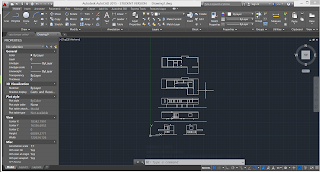
Trace the drawings of building in scale in autoCAD.

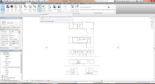
Import the CAD file into Revit.

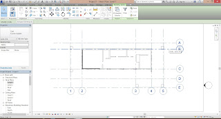
Create grid lines out of the major shape of the floor plan.


Based on the plan drawing, create a floor slab.
Extrude the walls out using the floor plan.

Adding one more level of view as the roof level.

Extrude all members out creating the general form of the whole building.


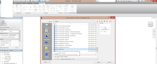
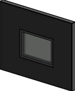
Family Member 1 - Window
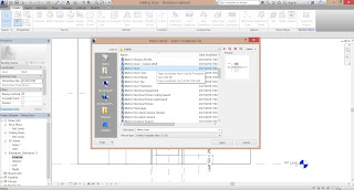
Create a new window family template.
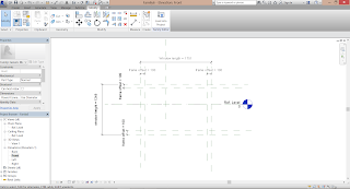
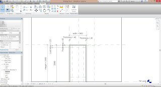
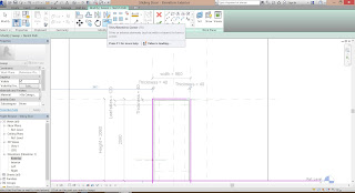
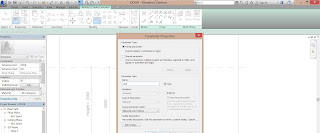
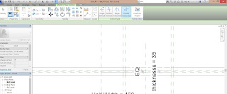
Plot out the Reference Plane(RP) of the dimensions and lock it to the void for window in the wall.
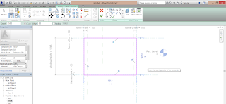
Create an extrusion out of the RP and lock them to line which act as the frame of the window.
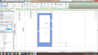
Create a Void form in the middle of the previous extrusion using the RP for frame thickness
Creating an empty void in the middle of the window frame.

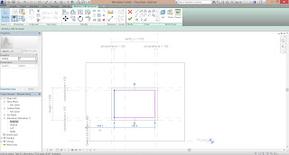
Another extrusion is added in the same plan as the Void Form which will be modified to be the glass panel.

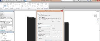
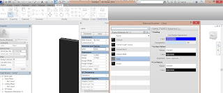
A new parameter is added under Material and Finishing.

And further added details as GLASS as material.
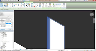
Input the material to the extrusion in the middle of void extrusion by the properties at the left.
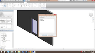
Load the family to the project file.

Window Family


Family 2 - Sliding Door
Create a new door family template.

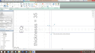
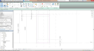
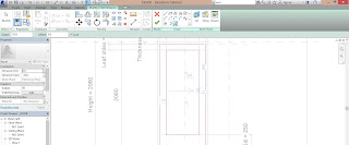
Plot the RP of the dimensions of the door labeled with parameters.

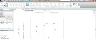
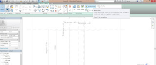
By using Sweep tool - Sketch Path - Pick lines, the RP for the door frame is selected.

Align the RP that has exceeded the bottom ground line to the ground line.

Lines that has exceeded has been trim using Trim tool.
Same steps from above starting from Sweep carried out again in the Ref Level view, creating the frame thickness.

Sub-categorize the frame as Frame/Mullion.

Offset and create a leaf  panel from the Ref Level view using Sweep tool.

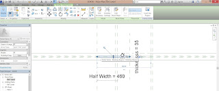
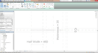
Add a new parameter as Half Width as the place where the sliding door is located when kept.

Extrude the leaf using extrusion tool.
Offset a new RP as Half Width with the half width of the leaf width.

A formula has been added to the family type under Half Width so that when the width changes, the half width changes as well.

Created the sliding door using Sweep tool.

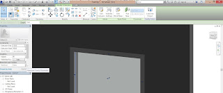
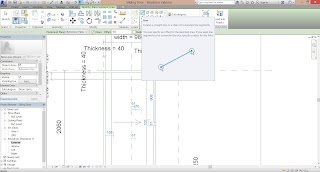
Create a symbolic line showing the direction of door opening to.


Add a double flip logo to the middle center RP of the leaf.
Plot out RP for the glazed panel of the leaf.

Sub-categorize the leaf stiles as Panel.

Create an extrusion in the middle and input material as Glass.

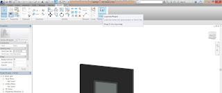
Load into project to be used.


PROJECT 3 Building Documentation
In this project, we are required to prepare a set of building documentation drawings using Revit's Documentation Components such as sheets, titleblock and etc.

These are the set of drawings that we requried to prepare:
Plans 

• Elevations
 • 2 Sections
 • 2 Callouts on sections 
• 1 Exploded isometric 
• Phasing (existing, demolished, new) 
• 1 Room Schedule showing area 
• 1 Finishing Schedule 
• 1 Furniture Schedule 
• Perspective renderings (2 exteriors + 2 interiors) 


Work in Progress:

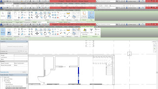
Load BIM A1 Metric Sheet given.


PLAN
Insert furniture to complete the floor plan.

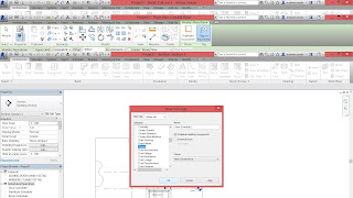
Create a furniture filter to indicate furniture.
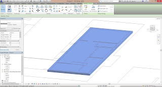
In visibility graphics, under filter tab override the furniture line color to RED to indicate furniture.
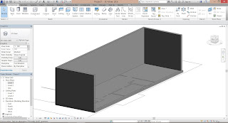
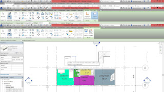
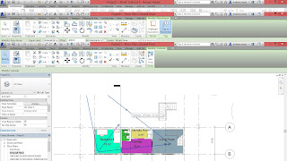
Use Rooms tool to tag and name every room in the floor plan.
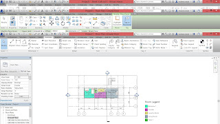
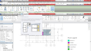
Under Annotation tab, use Color Fill Legend to create a legend and fills every room with different color.
Select the legend and edit scheme, change the category on the left to ROOMS to show colors on plan.
To hide the lines from other floor plan, set Underlay into NONE at floor plan properties.
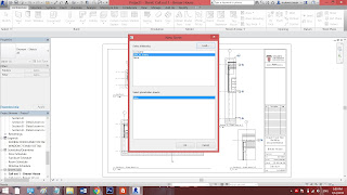
Drag the floor plan to the newly created sheet.
Select Hide Crop Region to hide the frame of the floor plan.
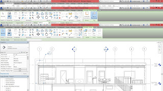
SECTION

Use Section tool to cut section from the floor plan.

Use Tag Room tool to indicate rooms in the section.


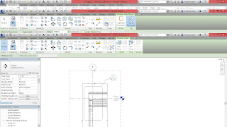
CALLOUT SECTION
Create callout from section.
Create another callout from a zoom-ed in section.


Add material and construction detail into the callout.


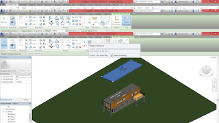
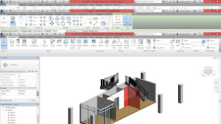
EXPLODED ISOMETRIC
Duplicate a 3D layer for isometric.
Use displacement tool to move and explode the building.

Add path to displaced element, indicating where it is.

SCHEDULE
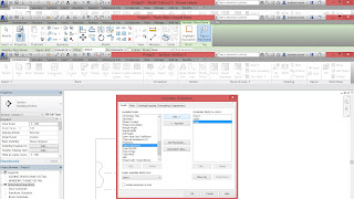
Create a new schedule, choosing the component i wanted to create a schedule, eg door, window, furniture.

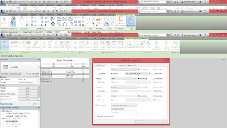
Add required schedule field that wanted it to be listed in schedule.
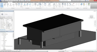

Edit its grouping and sorting to customize the schedule.


PHRASING
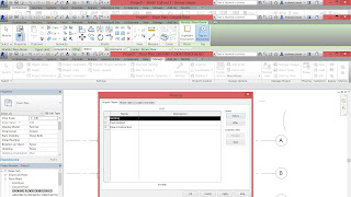
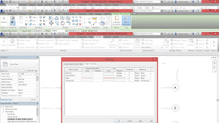
Create a new phrase under Manage tab - Phrases. 
Edit phrase to the example given.

Edit override graphics to indicate different stages of construction..
Duplicate 3 ground floor views for different phrases.


Change phrase filter to show existing structures.

Change wall setting to be existing and will be demolished.

Go to demolished floor plan, set phrase filter to show demolished.
Create a new wall and set phrases under new construction.

Set phrase filter to show new construction.


Duplicate 3 3D views showing each of the construction phrases, under same setting as the plans.


Renderings
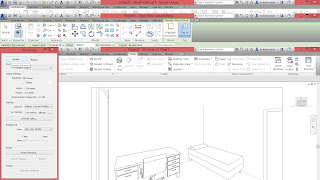
Set camera to desired view.

Under 3D showing the camera view, set render settings under VIEW tab.
Save rendered view using Save to Project.

0

Search