Introduction
The second project involves the production of Revit model of the selected architecture design using
Architectural Components such as Wall, Roof, Stairs, Floor, Curtain Wall, Doors and Windows.
Objectives of Project
The objectives of this project are as follows:
Understand and apply Revit Architecture’s modeling tools to generate a building model.
Learning Outcomes of this Project
• To learn access and build up databases to produce a simple BIM model and architectural
details complete with integrated information of materials; and their manipulation to have quick
options in a given situation.
• To use BIM as a design tool to create 3 dimensional models to analyze the aesthetics and
technical requirement.
Tasks - Methodology
1. Based on the selected architectural design, you are to generate a Revit model. The model must be
compliant withLOD200 requirements (refer Appendix 1).
2. Your Revit model must include at least TWO Revit Family components.
3. You are required to create a blog or Facebook album for public access.
The Work in Progress (WIP)
print screens and test renderings must be uploaded to the above online platform REGULARLY to show
progressive evidence of the working process.
It will serve as a communication and mutual learning
platform.
You are encouraged to visit your peers’ WIP and give constructive comments and
suggestions.
Submission Requirement
• Submit a folder containing the Revit file and Revit Family file to TIMeS.
• Upload Work in Progress (WIP) print screens and to your WIP website.
Building - Casa Breuer
Work in Progress
Whole building form
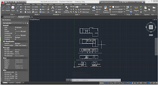 |
| Trace the drawings of building in scale in autoCAD. |
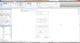 |
| Import the CAD file into Revit. |
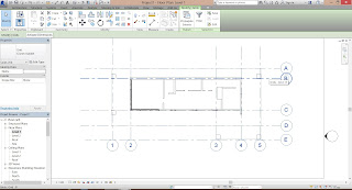 |
| Create grid lines out of the major shape of the floor plan. |
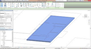 |
| Based on the plan drawing, create a floor slab. |
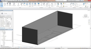 |
| Extrude the walls out using the floor plan. |
 |
| Adding one more level of view as the roof level. |
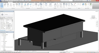 |
| Extrude all members out creating the general form of the whole building. |
Family Member 1 - Window
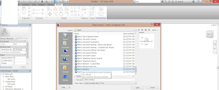 |
| Create a new window family template. |
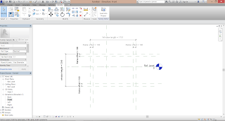 |
| Plot out the Reference Plane(RP) of the dimensions and lock it to the void for window in the wall. |
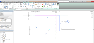 |
| Create an extrusion out of the RP and lock them to line which act as the frame of the window. |
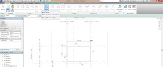 |
Create a Void form in the middle of the previous extrusion using the RP for frame thickness
Creating an empty void in the middle of the window frame. |
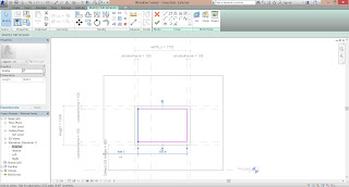 |
| Another extrusion is added in the same plan as the Void Form which will be modified to be the glass panel. |
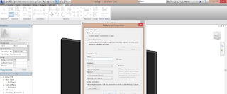 |
| A new parameter is added under Material and Finishing. |
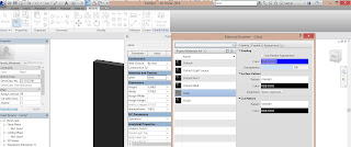 |
| And further added details as GLASS as material. |
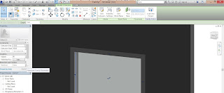 |
| Input the material to the extrusion in the middle of void extrusion by the properties at the left. |
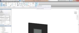 |
| Load the family to the project file. |
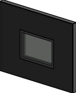 |
| Window Family |
Family 2 - Sliding Door
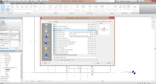 |
| Create a new door family template. |
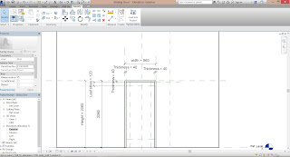 |
| Plot the RP of the dimensions of the door labeled with parameters. |
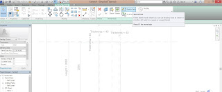 |
| By using Sweep tool - Sketch Path - Pick lines, the RP for the door frame is selected. |
 |
| Align the RP that has exceeded the bottom ground line to the ground line. |
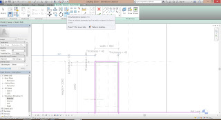 |
| Lines that has exceeded has been trim using Trim tool. |
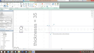 |
| Same steps from above starting from Sweep carried out again in the Ref Level view, creating the frame thickness. |
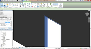 |
| Sub-categorize the frame as Frame/Mullion. |
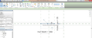 |
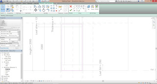
| Offset and create a leaf panel from the Ref Level view using Sweep tool. |
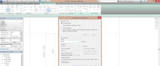 |
| Add a new parameter as Half Width as the place where the sliding door is located when kept. |
 |
| Extrude the leaf using extrusion tool. |
 |
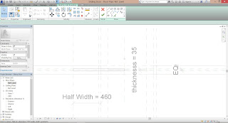
| Offset a new RP as Half Width with the half width of the leaf width. |
 |
| A formula has been added to the family type under Half Width so that when the width changes, the half width changes as well. |
 |
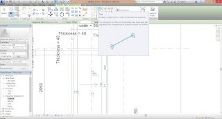
| Created the sliding door using Sweep tool. |
 |
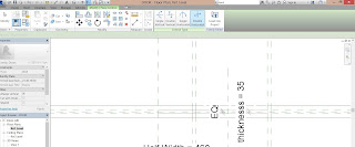
| Create a symbolic line showing the direction of door opening to. |
 |
| Add a double flip logo to the middle center RP of the leaf. |
 |
| Plot out RP for the glazed panel of the leaf. |
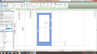 |
| Sub-categorize the leaf stiles as Panel. |
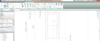 |
| Create an extrusion in the middle and input material as Glass. |
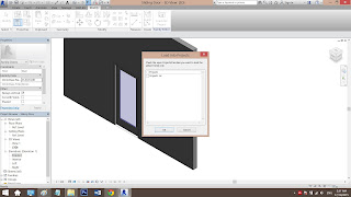 |
| Load into project to be used. |
PROJECT 3 Building Documentation
In this project, we are required to prepare a set of building documentation drawings using Revit's Documentation Components such as sheets, titleblock and etc.
These are the set of drawings that we requried to prepare:
Plans
• Elevations
• 2 Sections
• 2 Callouts on sections
• 1 Exploded isometric
• Phasing (existing, demolished, new)
• 1 Room Schedule showing area
• 1 Finishing Schedule
• 1 Furniture Schedule
• Perspective renderings (2 exteriors + 2 interiors)
Work in Progress:
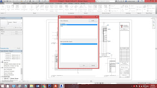 |
| Load BIM A1 Metric Sheet given. |
PLAN
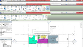 |
| Insert furniture to complete the floor plan. |
 |
| Create a furniture filter to indicate furniture. |
 |
| In visibility graphics, under filter tab override the furniture line color to RED to indicate furniture. |
 |
| Use Rooms tool to tag and name every room in the floor plan. |
 |
| Under Annotation tab, use Color Fill Legend to create a legend and fills every room with different color. |
 |
| Select the legend and edit scheme, change the category on the left to ROOMS to show colors on plan. |
 |
| To hide the lines from other floor plan, set Underlay into NONE at floor plan properties. |
 |
| Drag the floor plan to the newly created sheet. |
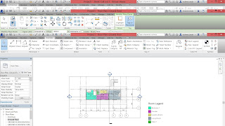 |
| Select Hide Crop Region to hide the frame of the floor plan. |
SECTION
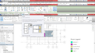 |
| Use Section tool to cut section from the floor plan. |
 |
| Use Tag Room tool to indicate rooms in the section. |
CALLOUT SECTION
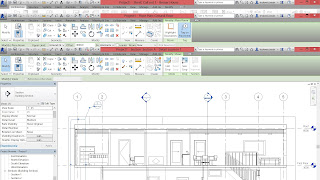 |
| Create callout from section. |
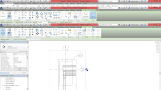 |
| Create another callout from a zoom-ed in section. |
 |
| Add material and construction detail into the callout. |
EXPLODED ISOMETRIC
 |
| Duplicate a 3D layer for isometric. |
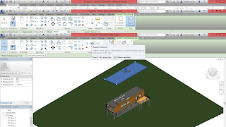 |
| Use displacement tool to move and explode the building. |
 |
| Add path to displaced element, indicating where it is. |
SCHEDULE
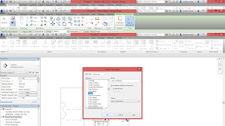 |
| Create a new schedule, choosing the component i wanted to create a schedule, eg door, window, furniture. |
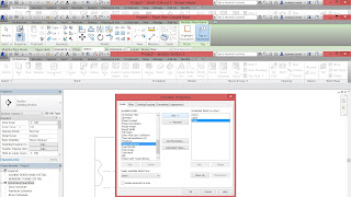 |
| Add required schedule field that wanted it to be listed in schedule. |
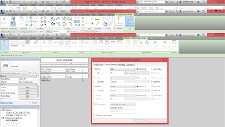 |
| Edit its grouping and sorting to customize the schedule. |
PHRASING
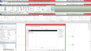 |
| Create a new phrase under Manage tab - Phrases. |
 |
| Edit phrase to the example given. |
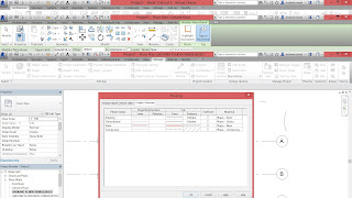 |
| Edit override graphics to indicate different stages of construction.. |
 |
| Duplicate 3 ground floor views for different phrases. |
 |
| Change phrase filter to show existing structures. |
 |
| Change wall setting to be existing and will be demolished. |
 |
| Go to demolished floor plan, set phrase filter to show demolished. |
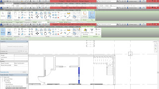 |
| Create a new wall and set phrases under new construction. |
 |
| Set phrase filter to show new construction. |
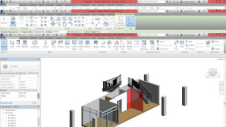 |
| Duplicate 3 3D views showing each of the construction phrases, under same setting as the plans. |
Renderings
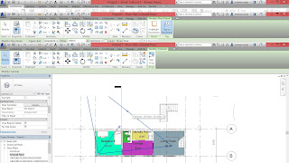 |
| Set camera to desired view. |
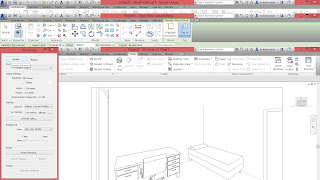 |
| Under 3D showing the camera view, set render settings under VIEW tab. |
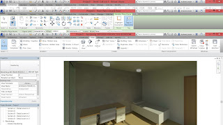 |
| Save rendered view using Save to Project. |
Introduction The second project involves the production of Revit model of the selected architecture design using Architectural Compone...


